Building services must play a major role in achieving the publicly stated aim of net-zero carbon by 2050. There are many ways to increase energy efficiency and reduce emissions in a building - and changes to how domestic and commercial hot water is supplied will play a significant role.
A major factor will be closer attention to delivery design and ensuing analysis of any given current system to facilitate the shift to low temperature domestic hot water (DHW). This has the potential to make an enormous contribution to overall energy reduction. The term “low temperature DHW” will sound and read like a contradictory term but it must be taken in the context of the current era, with energy and emissions under such scrutiny and concerns regarding scalding, especially for the vulnerable.
There are, however, a few concerns particularly related to health and safety that must be considered first.
Currently there are two major modes of supplying DHW:
- continuous flow (instantaneous) water heaters.
- storage tank water heaters, sometimes known as calorifiers
Both modes have their pros and cons, with the main differences are outlined below.
-
Have a limited e-store of water
-
When store depleted takes time to reheat before use
-
Require more plant room space
-
Weigh heavier
-
Can be more difficult to handle
-
Hot Water is only heated and provided upon demand
-
Endless supply of hot water provided that water and gas supplies are constant
-
Typically allow modulation and are more energy-efficient, especially the condensing versions.
-
Much lighter and require less space, time, labour costs and equipment to install.
Table 1 shows a comparative analysis between a continuous flow and storage water heater
As you can see from the data, the storage tank option tends to be less efficient and consume more energy. Once you factor in costs of replacement, a continuous flow heater is the more cost and energy-efficient option.
| Continuous Flow | Stored/reheated tank | |
|---|---|---|
|
Max Heat Input (kW) |
58.3 |
79 |
|
Max heat output (kW) |
56 |
56 |
|
Efficiency (Gross) |
96% |
82% |
|
1st hour flow rate @ 50°C rise (l/hr) |
960 |
1411 |
|
Storage/Cylinder (L) |
0 |
300 |
|
Continuous flow rate (l/hr) |
960 |
1111 |
|
Peak usage periods (hr) |
1 |
1 |
|
Number of peak usage periods |
3 |
3 |
|
Heating consumption(kW) |
58.3 |
79 |
|
Storage recovery time (mins) |
0.0 |
16.2 |
|
Storage recovery (kW) |
0.0 |
21.3 |
|
Storage loss (kWh) |
0 |
9.29 |
|
Secondary return system heat loss per hour (kW) |
10 |
10 |
|
Efficiency (efficiency curve of appliance) |
93% |
82% |
|
Appliance input for secondary system (kW) |
10.8 |
12.2 |
|
Secondary system operating time (hr) |
21 |
21 |
|
Reheat of secondary return (kWh/day) |
225.8 |
256.1 |
|
Consumption per peak period (kWh) |
58.3 |
79 |
|
Total consumption per day (kWh) |
400.7 |
566.4 |
|
Consumption per week (kWh) |
2804.9 |
3964.7 |
|
Annual CO2 carbon emissions (kgCO2e) |
26,889.5 |
38,007.3 |
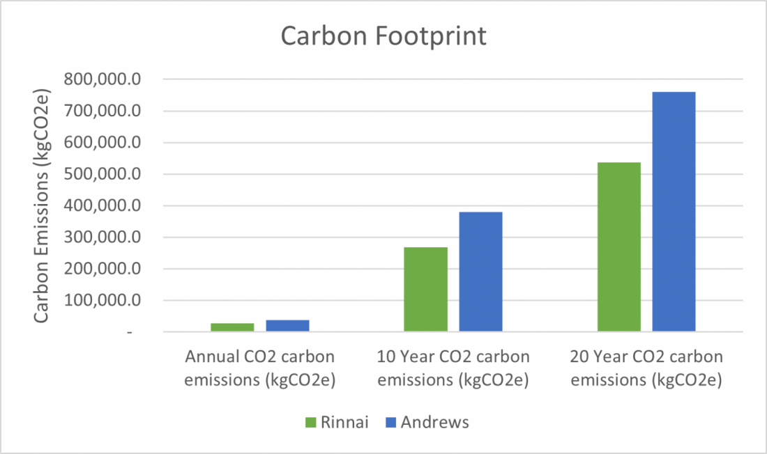
Continuous flow heaters are therefore generally better for reducing the carbon footprint as shown in Figure A, but with the correct measures in place it can be taken a step further.
When discussing temperature control of DHW, the risk of scalding must be considered, especially in the health and social care sector. This is an area that often provides care for individuals who may be more vulnerable to risks from hot water such as children, elderly people, those with less physical or mental ability or a sensory issue. According to the Health and Safety Executive (HSE), high temperatures over 44°C can create a scalding risk and as such water temperatures discharged from outlets accessible to those vulnerable or where there is the potential for full body immersion must not exceed this temperature. Engineering controls can be put in place to ensure this. These include thermostatic mixing valves (TMV’s) which should be placed as close to the outlet as possible or temperature-restricted or temperature accurate instantaneous water heaters.
National legislation underpins safety at work, and specific guidance for the control of L pneumophila in water systems is provided in the Health and Safety Executive Approved Code of Practice (ACOPL8) and its associated regulations, HSG274 Part 2. ACOP L8 governs the control of Legionella in water systems. Legionella – full name Legionella pneumophila – is a bacterium that causes, amongst other less serious conditions, Legionnaires disease, a potentially fatal form of pneumonia. Legionella bacteria are common in natural water sources but the conditions are rarely conducive to people catching the disease. This usually occurs in purpose-built water systems and the risk of being exposed to legionella increases in warm, stagnant water, passed to humans via breathing in minuscule, aerosol-like droplets of water.
Certain conditions support the growth of bacteria, such as a temperature range of 25°C - 45°C as well as the presence of certain deposits such as lime-scale, rust, sludge and organic matter can also increase this risk. Therefore, it is important to control the risk of exposure and to minimise it by introducing measures that restrict the growth of bacteria and reduce exposure. Traditionally this is done via temperature control, keeping stored water at least at 60°C and ensuring distributed water is supplied with 50°C water (55°C for healthcare) at outlets within 1 minute.
According to the ACOP L8 guidelines, continuous flow direct to outlet systems is low risk for Legionella, due to it allowing for a full turn-over of water volume, no stored water and accurate temperature control. However, this can be further reduced by implementing more preventative measures which include:
-
Good system design.
-
Avoiding dead legs (capped ends).
-
Keeping pipework as short and direct as possible, ensuring they are adequately insulated.
-
Maintaining cleanliness of system – hard water areas should be treated – so scale is reduced using innovative measures such as a zinc anode or a copper and silver ionization stagnant water.
-
Ensuring cold water comes from wholesome mains.
Due to their modulating nature, continuous flow heaters only provide an output in response to the water flow and temperature demand. This means that depending on what is required, the kW rating can range anywhere from a given maximum output to a minimum. For example, if a heater has a maximum output of 58.3kW and a 13:1 turn down ratio, it can potentially modulate down to a minimum of 4.4kW. This is a massive difference, resulting in a significant reduction in energy consumption and therefore emissions as it is not constantly operating at maximum power. A storage water heater, however, does not have the same ability as regardless of the capabilities of the heater, the water stored in the tank must be kept at a temperature of at least 60°C, requiring constant heating and wasted energy.
|
|
Rinnai N1600 |
|---|---|
|
Max Heat Input (kW) |
38.9 |
|
Max heat output (kW) |
37.4 |
|
Efficiency (Gross) |
96% |
|
1st hour flow rate @ 33°C rise (l/hr) |
960 |
|
Storage/Cylinder (L) |
0 |
|
Continuous flow rate (l/hr) |
960 |
|
Peak usage periods (hr) |
1 |
|
Number of peak usage periods |
3 |
|
Heating consumption (kW) |
38.9 |
|
Secondary return system heat loss per hour (kW) |
10 |
|
Efficiency (efficiency curve of appliance) |
93% |
|
Appliance input for secondary system (kW) |
10.8 |
|
Secondary system operating time (hr) |
21 |
|
Reheat of secondary return (kWh/day) |
225.8 |
|
Consumption per peak period (kWh) |
38.9 |
|
Total consumption per day (kWh) |
342.5 |
|
Consumption per week (kWh) |
2397.5 |
|
Annual consumption (kWh) |
125014.9 |
|
Annual CO2 carbon emissions (kgCO2e) |
22,984.0 |
Table 2 shows the output, consumption and running cost based on the same continuous flow water heater from earlier in the report when it has modulated down based on a temperature rise of 33°C and a flow rate of 16l/min. The annual savings shown in consumption and running costs are over 20,000 kWh and £1200, respectively. This saving amounts to almost 4 tonnes of CO2 emissions, which is more than what is produced by 2 return flights from London to New York per passenger. (Carbon Footprint, n.d.).
This can be taken further if the required flow rate is lowered to 10 l/min at 43°C (33°C rise). The results are displayed below in Table 3 and further reductions of 25,000 kWh and £1000 can be seen.
| Rinnai N1600 | |
|---|---|
| Max Heat Input (kW) | 23.92 |
| Max heat output (kW) | 23 |
| Efficiency (Gross) | 96% |
| 1st hour flow rate @ 33°C rise (l/hr) | 600 |
| Storage/Cylinder (L) | 0 |
| Continuous flow rate (l/hr) | 600 |
| Peak usage periods (hr) | 1 |
| Peak usage periods (hr) | 3 |
| Heating consumption (kW) | 23.92 |
| Secondary return system heat loss per hour (kW) | 10 |
| Efficiency (efficiency curve of appliance) | 93% |
| Appliance input for secondary system (kW) | 10.8 |
| Secondary system operating time (hr) | 21 |
| Reheat of secondary return (kWh/day) | 225.8 |
| Consumption per peak period (kWh) | 23.92 |
| Total consumption per day (kWh) | 297.6 |
| Consumption per week (kWh) | 2083.0 |
| Annual consumption (kWh) | 108611.8 |
| Annual CO2 carbon emissions (kgCO2e) | 19,968.3 |
Table 3: Analysis of continuous flow heater at 10l/min and 33°C temperature rise
Table 4: Summary data of energy and emission of storage vs continuous flow heater at different temperature rises and flow rates.
Striking a balance between providing low enough temperature water to reduce scalding risk and decrease consumption and emissions but high enough to minimise exposure to legionella is the aim and a continuous flow water heater equipped with accurate temperature control and proper system design is the best way to achieve this. The act of constantly recirculating high-temperature hot water alone has a high energy requirement.
One method that could be used in addition to normal operation is a pasteurization regime. This would consist of raising the water temperature very high to over 70°C, the point at which legionella bacteria are killed instantly, and flushing the system. This could be done when the building in question is not occupied, the water is returned to a safe temperature prior to occupancy and it could potentially allow for water to be supplied as low as 43°C during regular use, reducing consumption immensely.
A control routine reliant on water treatment could also permit a low-temperature system. A 2019 paper published by The American Journal of Infection Control entitled “Controlling Legionella pneumophila in water systems at reduced hot water temperatures with copper and silver ionization” studied the effectiveness of copper and silver ionization to control L pneumophila. The Great Ormond Street hospital building in question has effectively removed TMV’s from the system design by opting to supply water consistently at 43°C, instead relying on the copper-silver water treatment protection. They concluded that using this setup, not only had they saved money due to the associated costs of installed TMV’s but that the energy savings and reduction of carbon emissions were calculated to amount to “33% and 24% respectively compared to an equivalent temperature-controlled system”. In over 6 years, there have been no cases of legionella counts being detected. (Cloutman-Green, et al., 2019).
An instantaneous water heater with temperature control of ±1 and a high turnover rate would be the optimal solution. If set on a well-designed system with innovative measures taken to prevent scale and stagnant water, then the reductions in energy and emissions could be immense.
Article written by: Danny Madagwa, MEng, Rinnai.
References
Carbon Footprint. (n.d.). Retrieved from https://calculator.carbonfootprint.com/calculator.aspx?lang=en-GB&tab=3
Cloutman-Green, E., Barbosa, V. L., Jimenez, D., Wong, D., Dunn, H., Needham, B., . . . Hartley, J. C. (2019). Controlling Legionella pneumophila in water systems at reduced hot water temperatures with copper and silver ionization. American Journal of Infection Control.